From a technical perspective, files with the .uel extension are an exported package form of objects created within Tekla Structures that possess parametric intelligence. These files are generally classified as binary data formats at the operating system level. Although this binary structure prevents the file from being meaningfully read with standard text editors (such as Notepad++), it provides a highly accessible and efficiently processable dataset for Tekla’s internal database engine.
The content of a .uel file includes not only the geometry of a component, but also all the logical variables, formulas, alignment constraints, and user-defined attributes (UDA) associated with that geometry. This file format is a portable representation of the items found in the Applications & Components catalog of Tekla Structures. When a user needs to send a custom-developed connection detail or a unique profile section to a colleague, the software packages this object along with all its dependencies in the .uel format.
Within Tekla Structures, system components cover most standard structural connections; however, complex geometries and unique architectural solutions often require user-defined approaches. Custom components represent the process by which a user combines the basic geometric objects provided by the software (plates, beams, bolts, welds) to create a new, intelligent object. Once this process is completed, the created object is saved in the Applications & Components catalog and can be exported as a .uel file when needed.
There are four main types of custom components, and each carries different geometric rules and parametric structures when packaged in the .uel format:
Custom Connections:
Used to connect two or more parts. They include the interaction between the main part and secondary parts, as well as bolt groups and weld details. Within the .uel file, the distances and angular dependencies between these parts are stored in a formula-based manner.
Custom Details:
Typically define details added to a single main part (for example, stiffener plates added to the base of a column). How these details respond to profile changes in the main part is determined by constraints defined within the .uel file.
Custom Seams:
These are joints created along a line between two parallel parts. Panel wall joints or ridge details of purlins fall into this category.
Custom Parts:
These are assemblies formed by combining multiple objects but behaving as a single part (for example, a stair tread or a complex anchor group). These parts have placement properties similar to a beam and retain all their internal components when transferred to other models via a .uel file.
When a custom component is exported as a .uel file, Tekla Structures also scans for additional data files required for the component to function properly. For instance, if a parameter within a component reads values from an external .dat file via the fVF (file Value Find) function, that file is directly included in the .uel package. However, for this process to succeed, the relevant data file must be located within the model folder or in the CustomComponentDialogFiles subfolder.
Rather than simply copying a component, “publishing” it creates a critical distinction in maintaining corporate standards. In Tekla Structures, when you right-click on a component in the catalog and select the “Publish” option, the software prompts the user for a file name and save location. At this stage, it is strongly recommended to keep the file name identical to the original name in the catalog, as discrepancies in naming can make tracking and updating the component difficult in large-scale projects.
The publishing process also includes all metadata associated with the component. This metadata includes the component’s description, the tags used, and the thumbnail image displayed in the Applications & Components catalog. If multiple components are published together, Tekla generates a “catalog definition file” (ComponentCatalog.ac.xml). However, it should be noted that this XML file serves only as a directory guide; the actual objects themselves are still contained within the .uel files.
Advanced users and BIM managers typically manage components in groups rather than individually. In the Applications & Components catalog, when multiple components are selected and right-clicked, the “Publish separately” option can be used. This operation creates an independent .uel file for each component and allows these files to be stored in a centralized “Firm Folder.”
| Process Step | Description and Considerations |
|---|---|
| Component Selection | Multiple selection can be performed using the Ctrl key. |
| Right-Click Menu | The “Publish” or “Publish separately” command is used. |
| File Naming | It should be ensured that the file name matches the original component name. |
| Save Location | A secure directory outside the model folder should be selected. |
| Dependency Check | It should be verified that files containing the fVF function are in the correct location.. |
In Tekla Structures, profile catalog management is typically handled through .lis files; however, “Sketched Profiles” are an exception to this rule. When a user draws a unique cross-section using the Sketch Editor and saves it to the profile catalog, the export format for this profile is .uel.
Managing sketched profiles as .uel files means that they include not only the geometry itself, but also the drawing constraints and parametric variables that define that geometry. When a sketched profile is transferred to another model, the user can still modify its dimensions in that model via the Sketch Editor. During export operations from the profile catalog, the file type filter should be set to .uel.
| Object Type | Export Format | Purpose |
|---|---|---|
| Sketched Profile | .uel | Geometric and parametric section definition. |
| Standard Profile | .lis | Standard catalog values (HEA, IPE, etc.). |
| Parametric Profile | .clb | Formula-based profile definitions. |
| Entire Catalog | profiles.lis, profiles.clb, rules.lis | Complete database backup. |
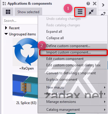
There are several ways to incorporate a .uel file into a Tekla Structures model. The most basic method is to press the “Advanced Features” button in the Applications & Components catalog and select the “Import” option. This process is manual and must be repeated for each model. However, in professional workflows, this process is automated to streamline component integration.
One of the most powerful tools for BIM managers is the XS_UEL_IMPORT_FOLDER advanced option. This option instructs Tekla Structures to automatically scan specified folders for .uel files and include them in the model when a new model is created.
The operating principle of this mechanism is as follows:
This method ensures that, especially in large teams, everyone has access to the same library of details. For existing models, however, this automatic import does not occur; the files must be manually imported or the catalog reloaded.
.uel files play a key role in Tekla Structures’ folder search hierarchy. To ensure company-wide standardization, these files are typically organized under the $XS_FIRM$ or $XS_PROJECT$ folders.
Folder Search Order and Priorities
When searching for a setting file or catalog, Tekla Structures follows a specific order that determines which setting overrides another:
.uel files should be strategically placed within this hierarchy. For example, a base plate detail used company-wide is stored in the Firm folder, while a custom corner connection developed for a specific client can be kept in the Project folder. This prevents unnecessary files from cluttering the model and ensures data integrity.
Version Compatibility and Critical Limits for .uel Files
Technological differences between Tekla Structures versions directly affect the portability of .uel files. The format follows a “forward compatibility” rule, meaning newer versions can read older .uel files, but there is no “backward compatibility,” so older versions cannot open files created in newer releases.
When a .uel file is exported, it contains a stamp indicating the Tekla version in which it was created.
From Older Version to Newer Version:
A .uel file created in Tekla Structures 2020 can be opened and used seamlessly in Tekla Structures 2026.
From Newer Version to Older Version:
A .uel file created in Tekla Structures 2026 cannot be opened in Tekla Structures 2022. The software will display an error indicating that the file is invalid or from a newer version.
Due to this technical limitation, the best practice when creating corporate component libraries is to design and export components using the oldest Tekla Structures version actively used by the company. This ensures that the library remains usable for all team members regardless of version differences.
When Tekla Structures is upgraded to a new version, some geometric core features used in custom components may have been improved. When a user imports a .uel file from an older version into a new model, the software may prompt: “Do you want to update the component?”
This update allows the component to take advantage of the performance and stability improvements offered by the new version. However, it should be done with caution, as it may introduce minor changes to the component’s original parametric behavior.
A common point of confusion among users is the assumption that macros and .uel files are the same. In reality, these two concepts are based on different technological foundations.
Macros:
Macros are script files created using the Tekla Open API in C# (.cs) or by recording user actions. They typically have the .cs extension.
.uel Files:
These are geometric and parametric object definitions, such as custom components and sketched profiles.
Despite their differences, both types of items appear side by side in the Applications & Components catalog and can work together. For example, a macro can be programmed to select a specific beam in the model and apply a custom component imported via a .uel file. In the Applications list, macros, plugins, and drawing extensions are grouped together for easy access and integration.
When a user starts recording a macro and calls a custom component (a .uel object) from the Applications & Components catalog, Tekla records this action at the code level.
If this macro is later shared with other users, the corresponding .uel file must also be installed on their system for it to function correctly. For this reason, comprehensive customization packages typically include both the .uel files and the macros that trigger them, ensuring seamless operation across different users and models.
When working with .uel files, the most common issues involve missing components, incorrect geometry representations, and version incompatibilities. Tekla Structures provides advanced diagnostic tools to detect and resolve these errors.
| Issue Description | Possible Cause | Recommended Solution |
|---|---|---|
| Component Not Visible in Catalog | Hidden items or missing ComponentCatalog.xml | Check the “Show hidden items” box or reload the catalog. |
| Geometry Errors (Solid Errors) | Intersecting objects or overly complex bindings | Run the “Diagnose & Repair” command and simplify bindings. |
| Parametric Values Not Working | Missing .dat or .lis files | Verify that files called by the fVF function are present in the model folder. |
| .uel File Cannot Be Imported | File may be from a newer Tekla version | Open the file in the version it was created in or a newer version. |
| Model Performance Is Very Slow | Too many handle-heavy contour plates or complex components | Use simpler rectangular plates instead of handle-heavy contour plates. |
Managing .uel files and custom components should be an integral part of a professional BIM management strategy. Here are some advanced tips for experienced users:
1.Simplicity Equals Efficiency:
Instead of creating a highly complex component, it is better to break the task into several simple components. Simple components are faster to model and less prone to errors.
2.Prefer Standard Profiles:
Whenever possible, use standard profiles within custom components. If a user-defined section is necessary, ensure that it is included in the .uel file.
3.Handle Management:
Use methods that minimize the number of handles when modeling objects. For example, using a two-point rectangular plate instead of a four-corner contour plate can reduce parametric bindings by half and improve model performance.
4.Naming Conventions:
Establish a consistent naming standard for your company. For instance, all corporate components could start with the prefix “TR_” or “FIRM_.” This makes catalog search and management much easier.
5.Model Templates:
Instead of importing frequently used .uel files each time, create an empty model template that already contains these files. Starting new projects with this template can save significant time.